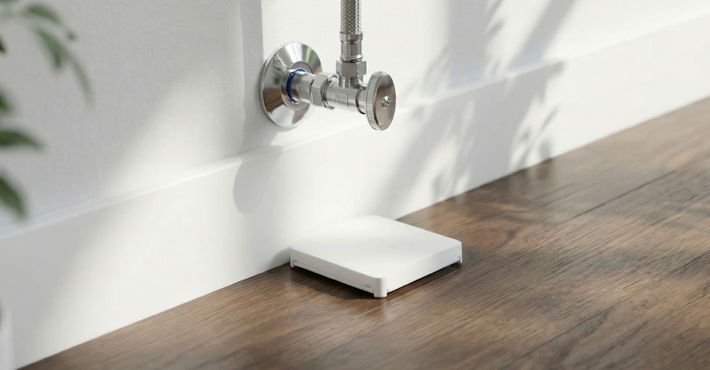
Installing Your Smart Leak & Freeze Detector
Smart Leak & Freeze Detector Installation Guide PDF
Installation Parts:
- Smart Leak & Freeze Detector
- (2) CR2450 batteries
- Two-sided tape
Tools Required:
- Flat-head screwdriver
The Smart Leak & Freeze Detector components:
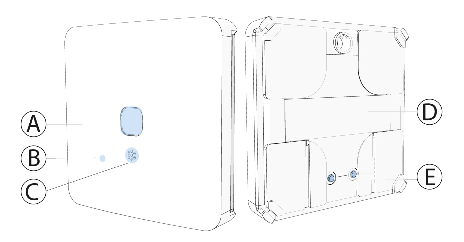
A - Multi-function button
B - LED
C - Buzzer
D - Nameplate
E - Electrodes
Pre-Installation Instructions
The following steps should be taken to initially power up the Smart Leak & Freeze Detector:
CAUTION: Do not replace the battery with an incorrect battery type. This device uses (2) CR2450 batteries.
Important: The batteries are shipped with reverse polarity, which means they are pre-installed in the device upside down. To power up the device for the first time, reinsert the batteries with the positive (+) symbol facing up.
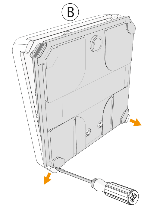
1. Insert a flat-head screwdriver carefully into the corner slot shown in the image below (A).
2. Apply gentle pressure to the screwdriver at an angle to lift open the device's inside cover tabs (B). Be cautious not to apply too much force to avoid breaking the tabs.
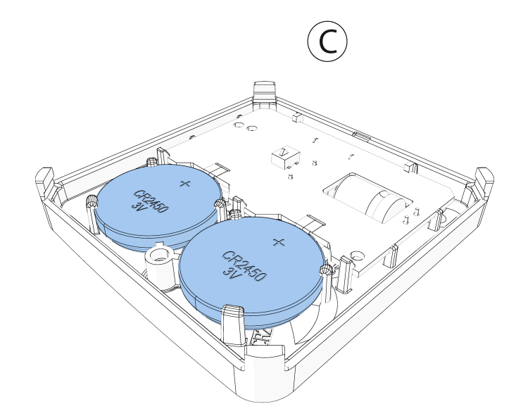
3. Repeat steps one and two for each corner tab, then remove the cover (C).
Removing the Cover
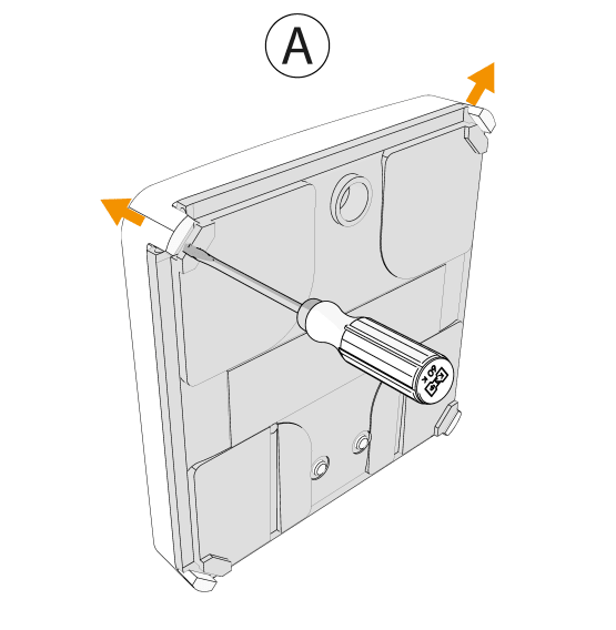
Note: Do not use an electric screwdriver to avoid damaging the plastic enclosure.
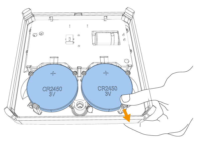
Releasing the Battery
Pull the front clasp back to take out the battery
Note: Do not use a screwdriver or other metal tool to remove the battery.
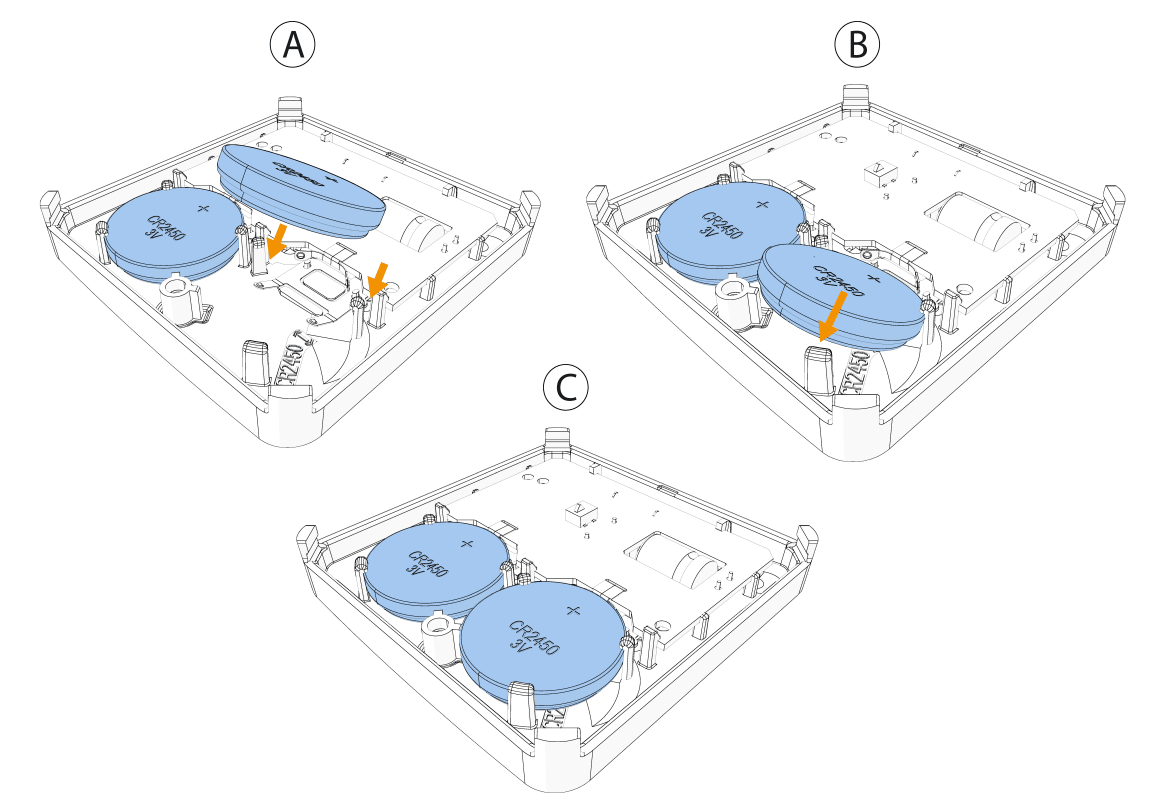
Insert the new battery at an angle under the two back clasps (A).
Push the battery down under the front clasp.
Note: When you insert the battery, ensure the (+) symbol is visible.
Inserting the New Battery
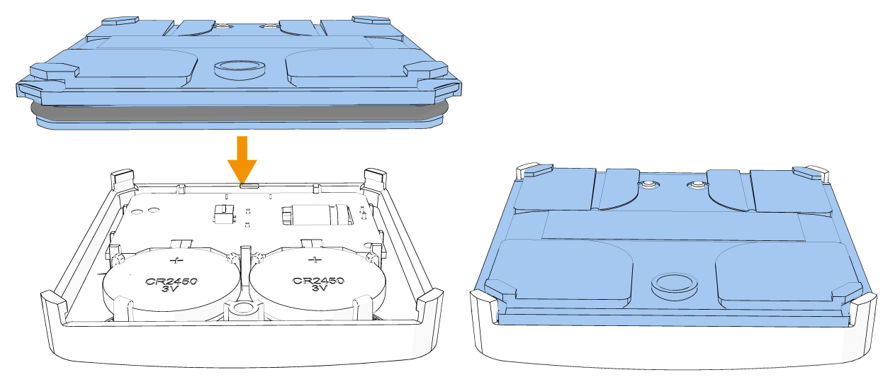
Snap the device cover back into place by following the image below. Do a visual check to ensure the cover is completely closed. After you restore a low battery, the system takes up to five minutes to clear the trouble.
Closing the Device Cover
Enrolling the Device
To enroll the Smart Leak & Freeze Detector with your control panel, please contact our Technical Support team at (800) 669-7779.
Configuring Device Parameters
If the option is available on your panel, configure device parameters on your control panel when you enroll your device.
See Table 1 for configuration options.
Option | Action |
|---|---|
Activation LED | Define whether the alarm LED indicator will be activated. Optional settings: Enable (default) and Disable. |
Buzzer | Define whether the alarm buzzer sound will be audible. Optional settings: Enable (default) and Disable. |
External Tamper | Define the settings for external tamper alerts. Note that internal tamper alerts are always enabled. Disabled: No external tamper alerts. Wall and Probe: External alerts are sent for both wall tamper and probe tamper events. |
Local Diagnostics Test & Signal Strength
After you power up or close the cover on the device, it automatically enters test mode for 15 minutes.
Note: To manually enter devices into test mode, refer to your control panel installation guide.
1. Remove the device cover from the base before starting the test. See Figure 2.
2. Close the cover to return the tamper switch to its normal position. The red LED will blink.
3. Wait for a few seconds until the red LED stops blinking.
4. Test the flood function. See Testing the Flood Function.
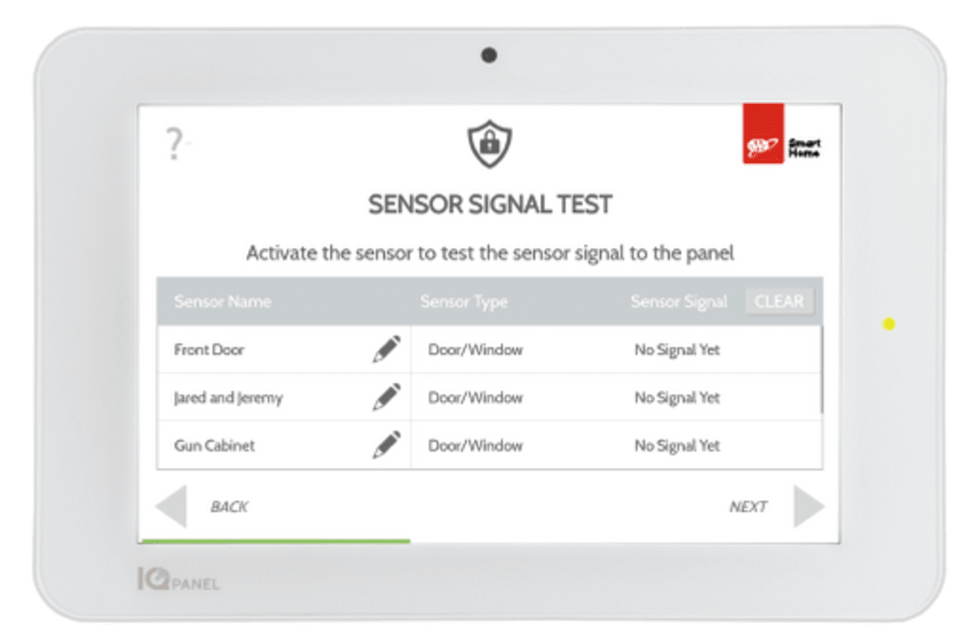
Checking the Signal Strength
1. Select Settings > Advanced on the IQ4 panel.
2. Enter the user code.
3. Select System Tests > PowerG Test.
4. Check the signal strength according to the LED. See the following table for details:
LED Response Reception | Reception |
|---|---|
Green LED blinks | Strong |
Yellow LED | Good |
Red LED | Poor |
No Blink | No communication |
Important: Ensure you have reliable reception. Poor signal strength is not acceptable. If you receive a poor signal from the device, relocate it and re-test until you get good or strong signal strength. Verify the signal strength with the control panel diagnostic test. For detailed diagnostics test instructions, refer to the control panel installation guide for your control panel. For UL/ULC installations, only strong signal levels are acceptable.
Testing the Flood Function
For the internal sensor or sensor probe, the water should make contact with both sensors. For the sensing cable, the water should make contact with any portion of the cable.
1. Choose option a or b.
a. Check the internal sensor by placing the device in a small container. Make sure it is stable.
b. Test the extension probe or sensing cable by placing the sensing probe or the sensing cable in a small container. Make sure it is stable. Please make sure the sensor probe or sensor cable is connected properly with the wall mount and device before beginning the test.
2. Run water slowly into the container until the level reaches the extension probe or sensing cable. Monitor the water level to ensure it makes contact with the sensor. Wait for the water tile to trigger the alarm on the control panel.
3. Remove the immersed portion of the water tile from the container carefully once the alarm on the control panel is activated.
4. Wipe off any excess water with care to remove moisture.
5. Dry the parts thoroughly. Use a soft, dry towel to wipe down the device, and extension probe or sensing cables.
6. Allow the device, and extension probe or sensing cables to air-dry completely. After the device, and extension probe or sensing cables are completely dry, carefully place the device back in its designated location.
Testing the Freeze Detection Function
If the freeze feature is available, perform the following steps to test the freeze detection function.
1. Place the water tile in a dry area of the freezer.
2. Wait for the temperature reading of the water tile to drop below 5 ̊C (41 ̊F) for low temperature to trigger the freeze alarm on the control panel.
3. Remove the sensor from the freezer with care once the alarm on the control panel is activated.
4. Wipe off any excess water gently to prevent moisture from lingering.
5. Dry the sensor thoroughly. Use a soft, dry towel to wipe down the sensor. Ensure all surfaces, including connectors and openings, are free from moisture.
6. Allow the sensor to air-dry completely. After the sensor is completely dry, carefully place it back in its designated location.
Mounting the Device
• Do not install near high-voltage electrical lines.
• Do not install outdoors.
• Place the device on the floor or mount it on the wall with a bracket at any height. Ensure the device is in the correct location, ideally near potential flood sources.
Note: The bracket is not intended to be submerged in water.
CAUTION: The included double-sided tape may damage your flooring finish. Johnson Controls will not be held liable for any damages incurred. If you choose to use the double-sided tape for mounting the device, we strongly recommend consulting your flooring manufacturer for appropriate adhesive options.
Important: Insert the batteries before mounting the device. See Pre-installation Instructions or Inserting the New Battery in the device.
Using the optional double-sided tape:
1. Peel the release liners off the two adhesive tape pads.
2. Attach the two tape pads to the back of the device.
Optional: Attaching Tape
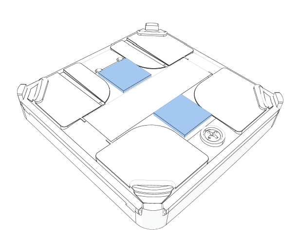
CAUTION: Do not cover the electrodes.
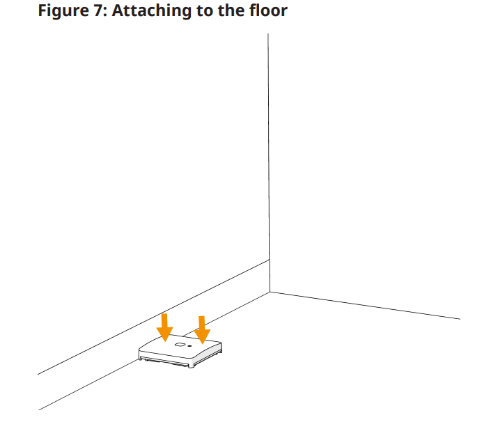
3. Attach the device to the floor in an area that is likely to experience flooding.
4. Hold the device in place for one minute to ensure it is attached.
Attaching to the Floor
Optional: Mounting the Device with a Wall Mount Bracket and Sensor Cable
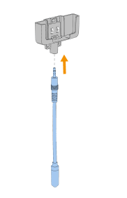
Perform the following steps to mount the device with a sensing cable:
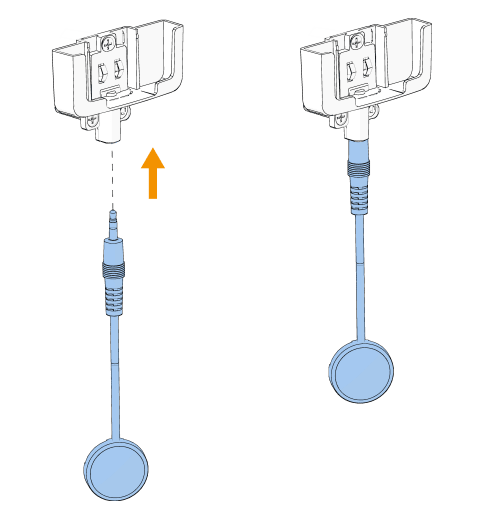
Connect the sensing cable to the bracket.
Connecting the Cable To the Bracket
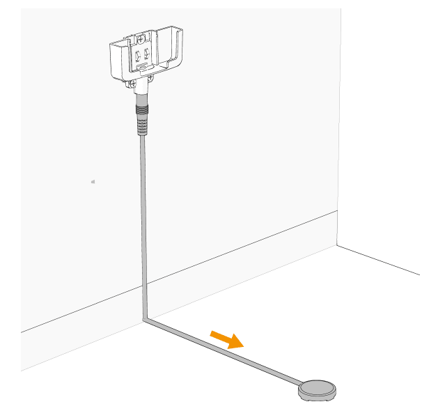
Lay the sensing cable on the floor.
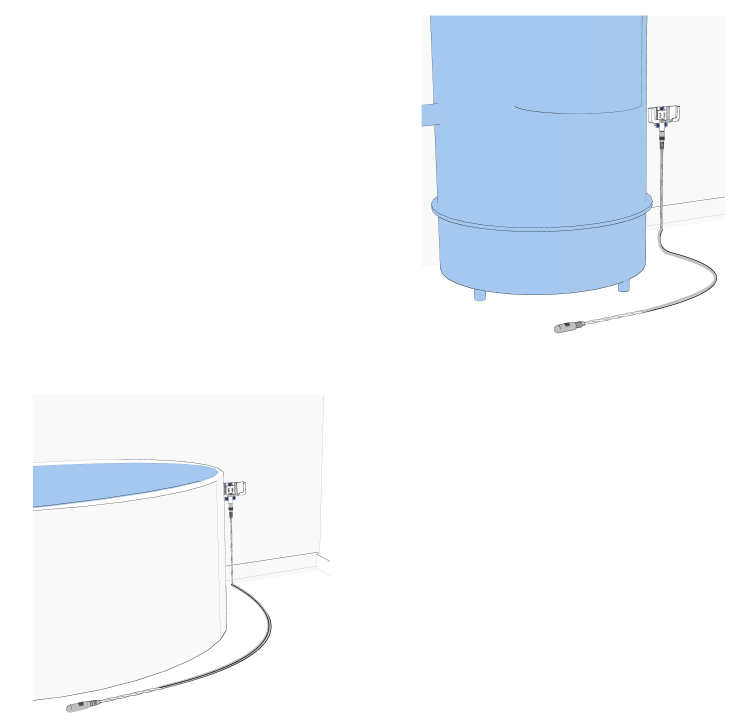
Optional: Use the supplied clips to fix the cable to the floor or surface. Keep approximately 40 cm (16 in.) distance between each clip.
Attach the bracket to the wall with three screws. Recommended screw size is Phillips #6 x 1 in. long. Do not use an electric screwdriver.
Note: When choosing a mounting location, ensure there is sufficient height left below the bracket for the connector of sensing cable.
Note: For UL-2017 compliance, screws must be installed.
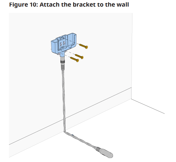
Note: Use only the screws supplied in the kit.
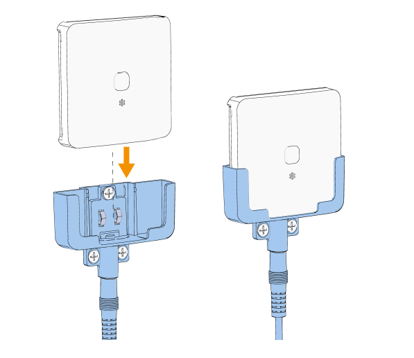
Slide the device into the bracket until it clicks into place.
Inserting the Device into the Bracket
Optional: Mounting the Device with the Wall Mount Bracket and Sensor Probe
Perform the following steps to mount the device with an external probe. Connect the external probe to the bracket.
Connecting the External Probe to the Bracket
Lay the external probe on the floor to set it in place.
Secure with tape.
Attach the bracket to the wall with the three screws provided in the kit.
Note: Use only the screws supplied in the mounting kit.
Insert the device into the bracket.
Flood Alarm Events
• The Smart Leak & Freeze Detector can detect leaks from all water-based liquids, except for distilled water.
• When a flood alarm is triggered, the Smart Leak & Freeze Detector indicates the event on the control panel, and the device LED blinks red while the buzzer emits an audible beep.
• To silence the Smart Leak & Freeze Detector buzzer during a flood alarm, press and hold the multi-function button until you hear two beeps. The Smart Leak & Freeze Detector buzzer remains muted until the device's status returns to normal, then the buzzer reactivates.
• After a flood alarm event, please refer to Testing the Flood Function for instructions on how to reset the Smart Leak & Freeze Detector.
Maintenance
To ensure optimum performance, complete the following maintenance tasks periodically:
• Wipe the water tile and its sensors with a soft, dry cloth to remove dust and debris.
• Avoid harsh chemicals when cleaning. Do not use abrasive cleaners or solvents that may damage the device.
• After each flood detection, the device, sensing cable, and external probe should be cleaned and dried. Otherwise, the unit may not operate, as intended, due to the nature of different liquids.
• Check the battery levels regularly to ensure the detector remains operational.
Troubleshooting
Problem | Solution |
|---|---|
Not powering on | Check battery installation: Ensure that the batteries are installed correctly. Remove the batteries and reinsert them in the correct orientation. Inspect batteries: Check if the batteries are old or depleted, and replace them with new recommended batteries if necessary. |
Low battery notification | Promptly replace: Replace the battery, as soon as possible, to maintain device functionality. Delaying battery replacement could result in loss of detection capabilities. |
Connectivity issues to the control panel | Signal strength: If you receive a Low Signal or No Signal alert during panel signal testing, try relocating the water tile to a different position where it may receive a stronger signal. Consider repeaters: If connectivity issues persist, consider using a PowerG or PowerG+ repeater to enhance the signal strength between the water tile and the control panel. |
Device does not trigger during an alarm | Placement verification: Ensure the water tile is installed in a suitable location where flooding is likely to occur, avoiding areas with minimal water exposure. Clean sensor, probes, and cables: Check that the sensor and, if applicable, the probes, or any sensing cables are clean and devoid of debris. Use a soft, dry cloth to wipe them down. Conduct Function Tests: Follow the testing procedures outlined in this user manual to verify water tile functionality. Tampering Test: To test the sensor's responsiveness, remove the battery cover to simulate a tamper condition. |
Flood false alarms | Humidity check: Confirm that the water tile is not situated in an excessively humid environment, which could trigger false alarms. If residual humidity or water droplets are present, clean the sensor, probes, and sensing cables, then relocate the sensor to a drier area. Dry sensor and probes: Ensure that the sensor, probes, and sensing cables are completely dry and not in contact with water as this will trigger an alarm. Check probes and cables: Inspect if the external probes and/or cables are cut or crushed. |
Buzzer does not sound when water is detected | Mute settings: Verify that the buzzer is not set to mute. If it has a mute function, ensure it is disabled. Perform buzzer test: If your control panel has a buzzer test feature, use it to ensure the buzzer is functioning properly. |
Control panel indicates tamper | Secure battery cover: Ensure that the battery cover on the sensor is properly closed and secured. Check probes and cable attachment: Confirm that the probes and sensing cables are correctly attached and not loose as this can trigger a tamper alert. Inspect probes/cables for damage: Check if the external probes and/or cables are cut or crushed. |
Leak alarm triggered after resetting the water tile | Investigate leak cause: The cause of the leak alarm may still be present. Inspect the area for ongoing leaks or sources of water. Check for moisture: Ensure that the sensor, probes, and sensing cables are completely dry. If they are still wet, the alarm will continue to trigger. Inspect for damage: Examine the sensor and its components for any signs of damage. If any part is damaged, it may need to be replaced. |
Cannot locate the device | If your control panel has the feature, use TEST LED and TEST BUZZER to locate the device. |
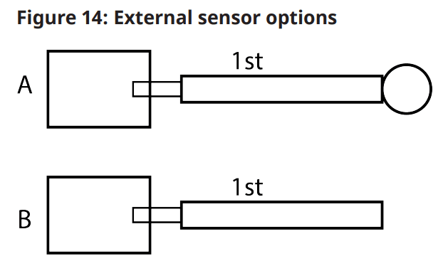
Event Trouble Notification for External Sensor Connection Options
See the following image and table for external sensor connection options.
Important: It is not recommended to connect the external sensor probe to the sensor cable. It is not advised to use the sensor cable from a third party to connect to the wall mount bracket or sensor cable. These third-party connections could void the device's warranty
External sensor options
Resetting To Factory Default Settings
1. Press and hold the multi-function button for at least two seconds until the LED shows a steady orange light.
2. Release the multi-function button quickly, then press and hold the button again for 15 seconds until the LED turns red and flashes three times to indicate a reset to factory default.
Note: After a device is reset to factory default, delete it from the panel and re-enroll the device.
Other Device Install Guides
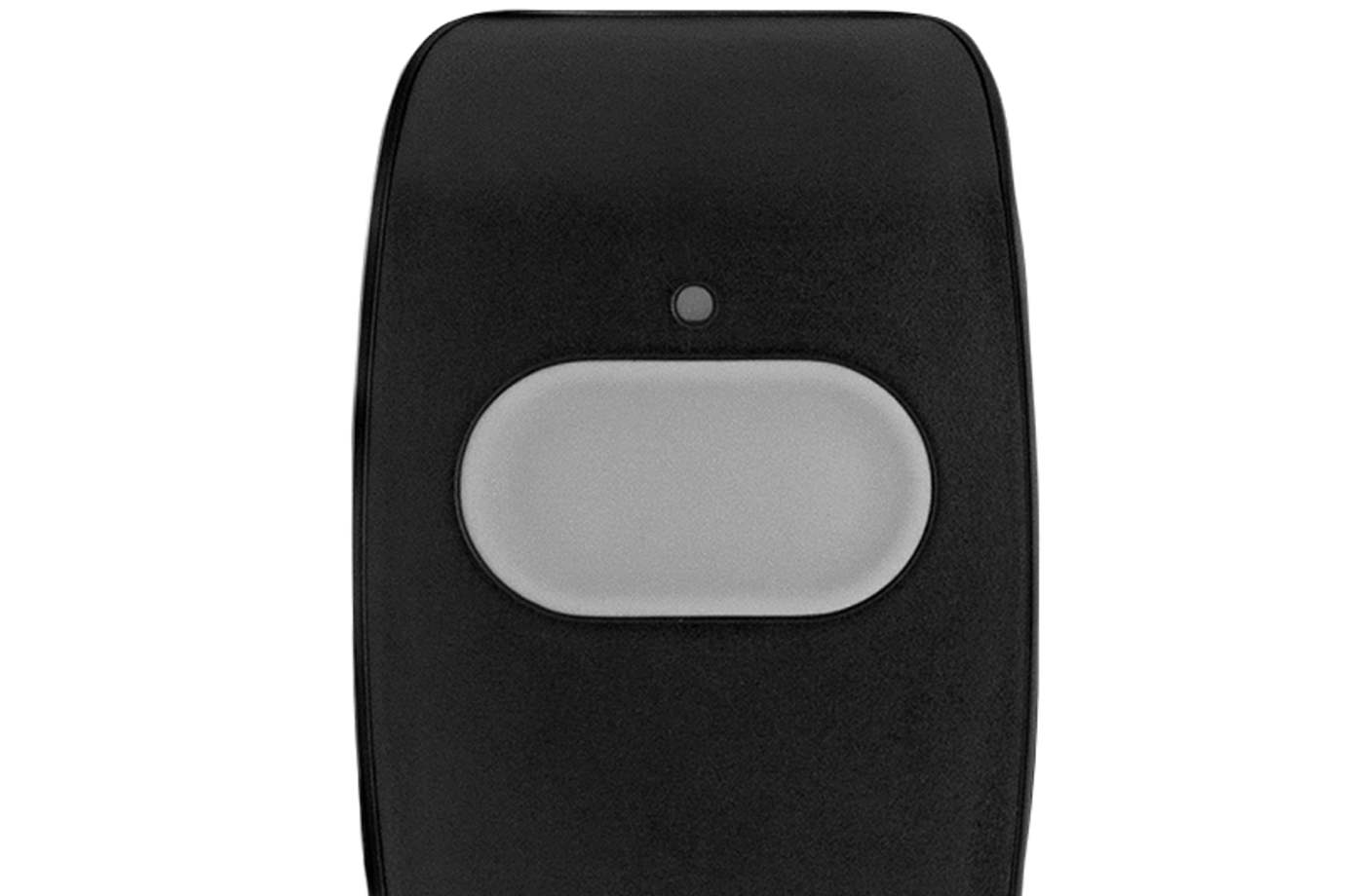
When pressed within range of your panel, the panic button alerts your system to dispatch medical, fire, or police first responders in case of an emergency.
Congrats on installing your AAA Smart Home Security system! All you need to do now is call us at (855) 933-4393 (Phone Number) (Phone Number) (Phone Number) (Phone Number) to get your system and monitoring up and running. We’re available Monday - Friday (7:30 am - 6 pm PST) and Saturday (8 am - 6 pm
We offer basic and smart home security systems with professional monitoring for as low as $19.99/month. Keep your home safe and get your free quote today.

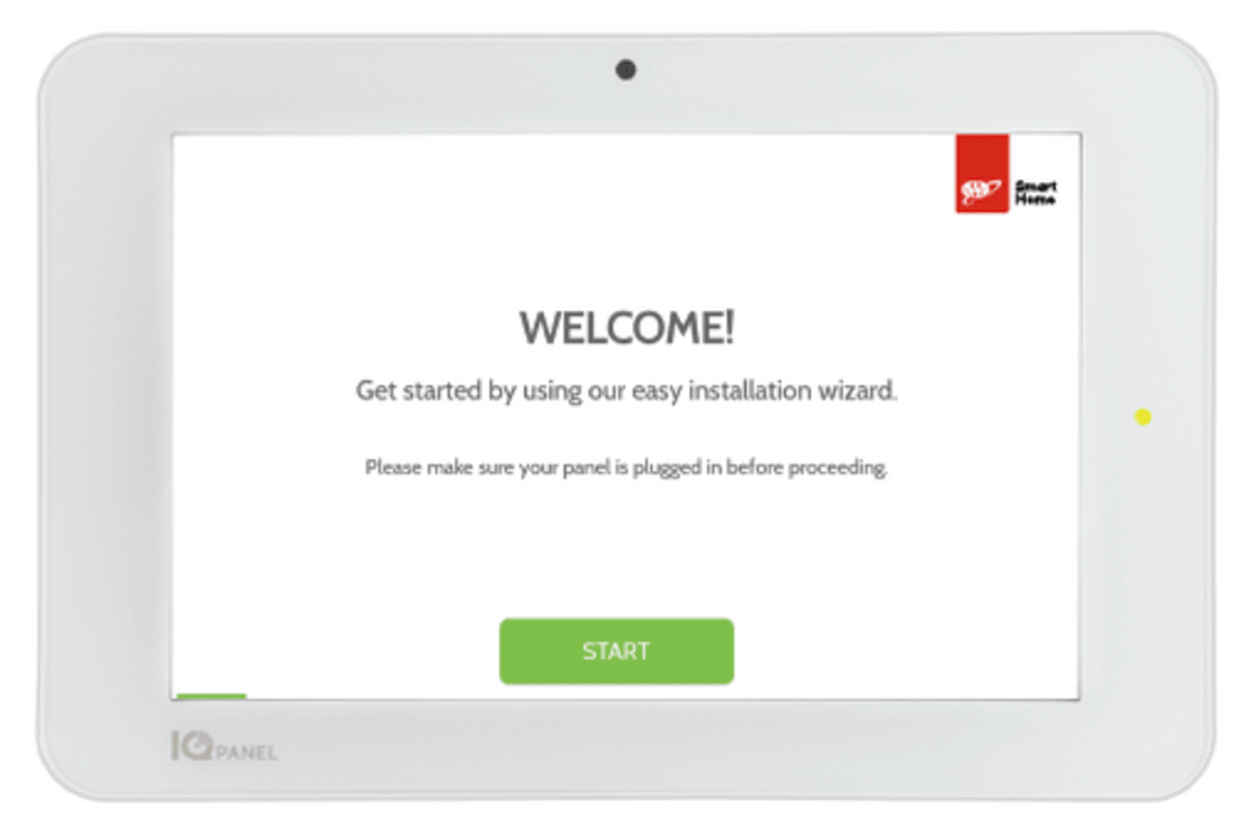
Before setting up your AAA Smart Home control panel, make sure you have all the components needed and you have read over the documentation.
With our most advanced outdoor camera yet, the Premium Outdoor Camera provides 24/7 recording capabilities, enhanced night vision, proactive deterrence by automatically emitting loud noises if an unwanted visitor is on your property, access to two-way audio, and intelligent video analytics.